Kate-1 TelemetryPro® Transmitter
PLEASE NOTE: Kate-1 is now obsolete, out-of-production and no longer available.
|
|
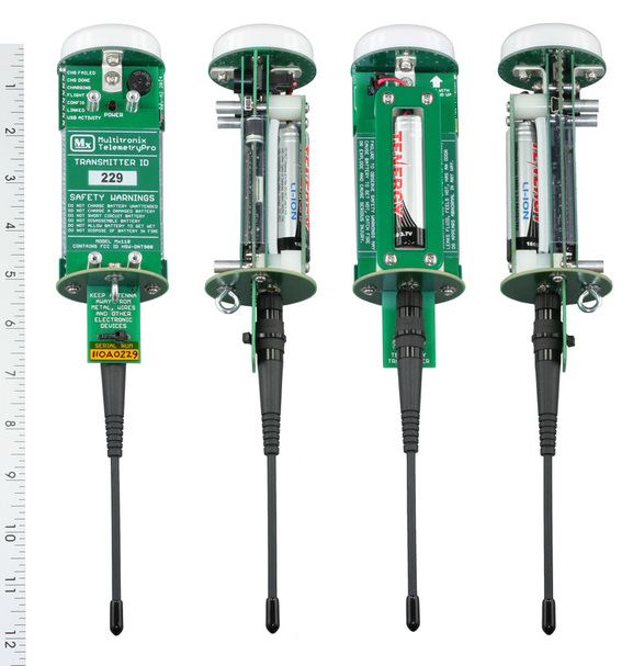
The Kate-1 transmitter is a finished product that is ready to fly, right out of the box. It is not just a bare board that requires a custom mounting sled or bulkhead to be built for it. The antennas, battery and power switch are fully integrated into the finished unit. There is no battery mounting, no switch mounting, no antenna mounting nor wiring harness to worry about. It is a self contained unit that is easy to move from one rocket to another.
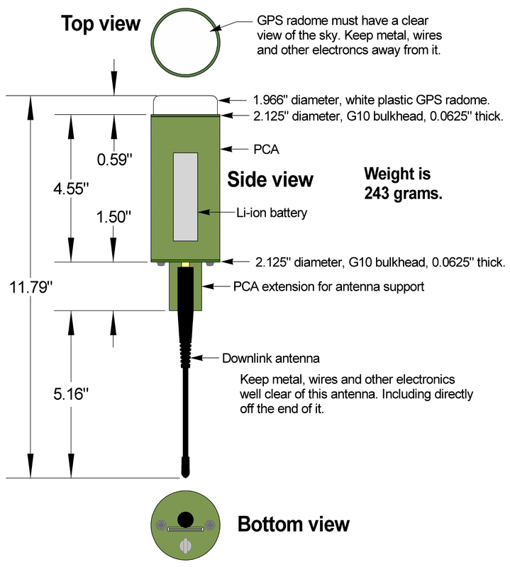
The top end of the transmitter has the GPS antenna protected inside a radome. The downlink antenna extends out the bottom of the transmitter. LED status indicators are lined up vertically along the upper left edge on the front side and clearly labeled. There is also an audible beeper that can be heard outside the rocket to confirm the unit is on and operating. It beeps out the transmitter ID code and repeats it every so often in case it is needed and to serve as an "I am still alive" indicator. The transmitter can be powered-on using an induction turn-on coil. There is no need to provide an access hole for the power switch. The transmitter can be powered-off by sending a shutdown command from the receiver. |
The transmitter uses a one watt, 900 MHz transceiver that allows for two way communications. No HAM license is required. Transmit power is adjusted automatically for optimum RF link and battery life. Range exceeds 500,000 feet. It uses a Ublox-7 GPS with a large, high gain antenna and preamp for best possible satellite reception. The GPS updates position fixes five times per second. There is also a 50 G accelerometer that is read 100 times per second. (Recommend 45 G max thrust to allow for operational margin.) All GPS data, accelerometer data and other readings like battery voltage and temperature are saved into on-board flash memory for downloading after the flight. This data is also transmitted to the ground at five updates per second. A USB interface is built-in and used for downloading flight data and for charging the Li-ion battery. The battery provides more than five hours of standby time prior to flight.
Any transmitter can be used with any receiver by setting their ID codes to match. A transmitter can also simultaneously link with multiple receivers in order to provide tracking redundancy during a flight.
The transmitter power button can be used to turn the unit on or off. Press and hold for two seconds to turn the transmitter on. Press and hold for six seconds to turn the transmitter off. Or better yet, use the optional turn-on coil.
Transmitter firmware can be updated over the USB interface using the TelemetryPro software program. This allows the unit to be easily updated with new features when new firmware is released.
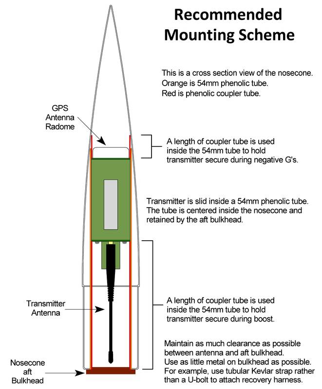
The transmitter is designed to be mounted inside a standard 54mm phenolic or fiberglass tube. Phenolic or fiberglass coupler tubes above and below it should be used to hold it in place within the main tube. For best results, it should be mounted in the nosecone. It will not perform properly if mounted inside carbon fiber tubes or inside a carbon fiber nosecone. Carbon fiber will absorb the transmitted signal! Some fiberglass tubes that are black can also attenuate the signal if they contain a conductive form of carbon or graphite to make them black.
The transmitter must be mounted with the GPS facing up. This is required for proper operation of the GPS and the accelerometer.
Some nosecones come with a metal tip. This is not a problem as long as the TelemetryPro transmitter is mounted about three or four inches behind the tip. Doing so allows the GPS antenna on top of the TelemetryPro transmitter to "see around" the metal tip to receive signals from the GPS satellites
|
MAC Performance Rocketry sells some very nice "Ready-to-Fly" nosecones that are specifically built to hold the TelemetryPro transmitter. They are available in 3" and 4" sizes in either fiberglass or plastic. They use a PVC threaded closure with a Kevlar lanyard. This eliminates any metal parts from being near the transmitter downlink antenna yet is very secure.
The fiberglass nosecone is filament wound and has a canvas phenolic coupler that is exceptionally strong. The tip on the fiberglass nosecone is aluminum These are high quality nosecones that eliminate the need to build your own. They are Multitronix approved! |
|
Nosecone Anchor Mount Construction
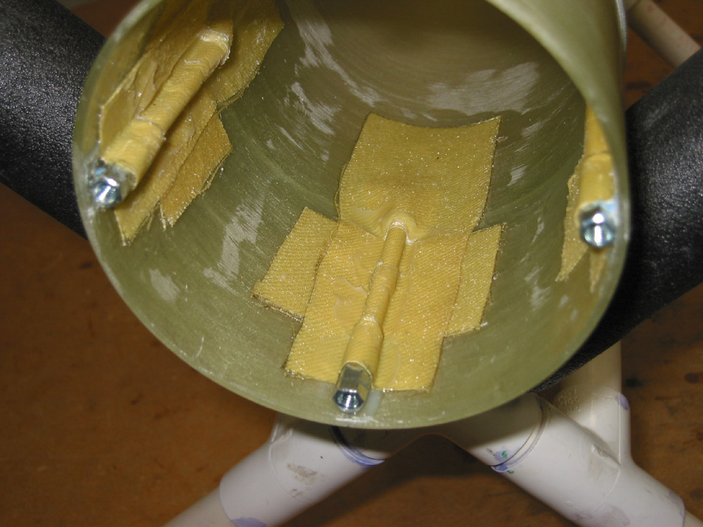
Some nosecones come with a threaded metal rod that runs down the center of it to hold the aft bulkhead into place. This is not compatible with the TelemetryPro transmitter for two reasons. First, the transmitter will not fit. And secondly, a metal rod is conductive and will degrade the performance of a radio downlink antenna located near it. (This is true for any downlink transmitter antenna. Not just TelemetryPro.) A method for eliminating the threaded rod is shown in this photo. It uses Kevlar stripes saturated in epoxy to hold some threaded mounting anchors to the inside surface of the nosecone shoulder. Short screws can then be used to hold the bulkhead in place. Full details on how to construct this are presented at the link below. |


